
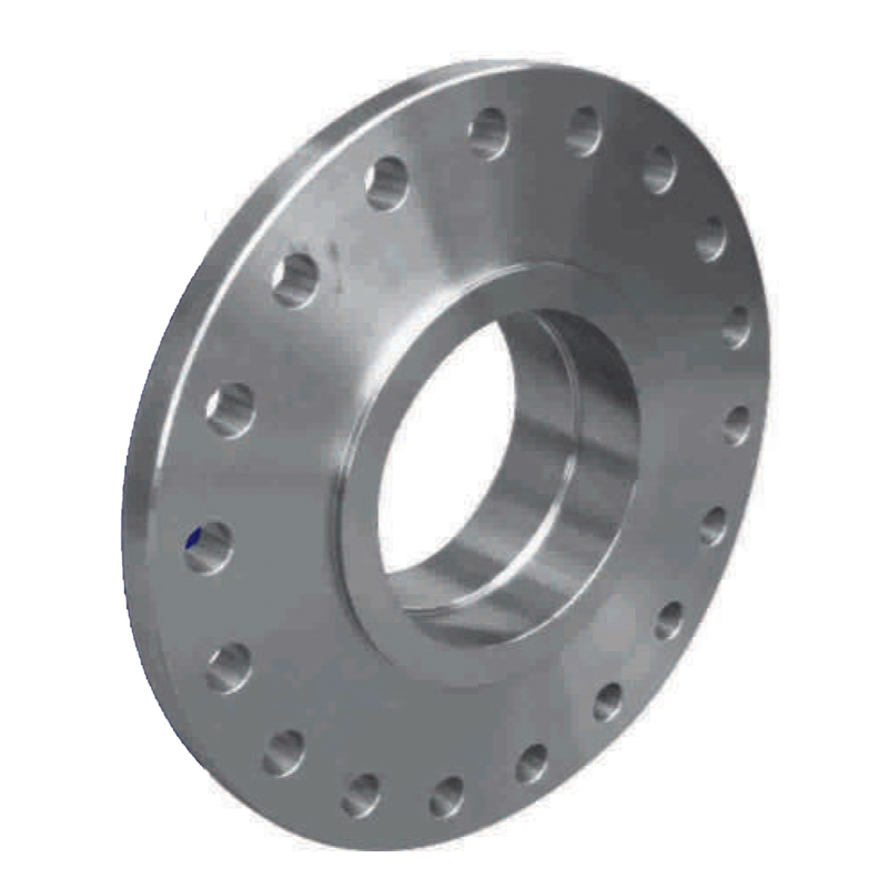
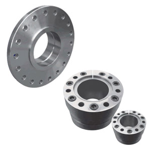
Rigid Flange Couplings
Rigid Flange Couplings are manufactured for Rotech Systems in South Africa according to international standards. Rigid flange couplings are primarily used on conveyor belt drives holding the gearbox shaft to the drive pulley shaft, using two rigid flanges with the 1014 type locking elements, locking each flange to the respective shaft and then bolted together making it a parallel rigid coupling connection.
| Size | Shaft Diametre (mm) | Weight (kg) | Torque (Nm) | Flange Connecting Bolts | Number of Bolts |
| 170/260 | min. 50 | 32 | 6 300 | M14 x 16 | 8 |
| max. 70 | 30 | 10 000 | |||
| 200/320 | min. 70 | 39 | 16 000 | M16 x 75 | 8 |
| max. 90 | 37 | 20 000 | |||
| 230/400 | min. 95 | 47 | 28 000 | M24 x 100 | 8 |
| max. 115 | 45 | 35 500 | |||
| 270/400 | min. 115 | 55 | 45 000 | M24 x 100 | 8 |
| max. 140 | 51 | 56 000 | |||
| 330/560 | min. 140 | 112 | 90 000 | M30 x 120 | 18 |
| max. 170 | 105 | 112 000 | |||
| 390/560 | min. 170 | 137 | 160 000 | M30 x 120 | 18 |
| max. 210 | 125 | 200 000 | |||
| 430/630 | min. 170 | 160 | 160 000 | M30 x 130 | 18 |
| max. 210 | 148 | 200 000 | |||
| 470/630 | min. 210 | 199 | 255 000 | M30 x 130 | 18 |
| max. 250 | 183 | 315 000 | |||
| 510/710 | min. 250 | 299 | 375 000 | M30 x 130 | 24 |
| max. 270 | 249 | 400 000 | |||
| 550/710 | min. 270 | 286 | 475 000 | M30 x 130 | 24 |
| max. 290 | 275 | 500 000 |
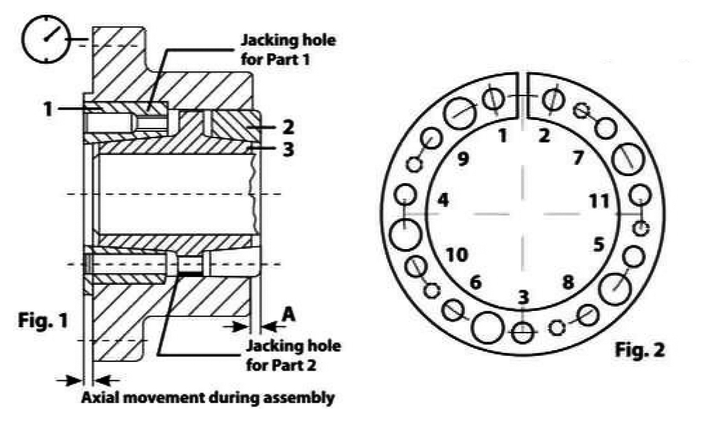
Sequence torque – Installation
Assembly
- Release all bolts a few turns and transfer at least 3 bolts into each of the tapped holes of part 1 and 3 in order to keep a gap between pans 1 & 2 spaced from 3. The 1014 has a self locking taper.
- Lubricate the locking ring (machine oil) before installation (do not use Molybdenum disulfide MoS2).
- After installing onto shaft, transfer the bolts from the jacking holes In parts 1 & 3 into the taped holes of part 2.
- Before tightening the bolts, turn the connecting flange until the split is vertical on the topside of the shaft.
- Hand tightening the bolts progressively, starting next to the split and alternating diagonally. Check the run out and dimension A for equal distance. Correct any misalignment. At this point the run out should not exceed 0.05 at the face of the coupling. Excessive misalignment can cause permanent damage to the unit.
- Then proceed with a torque wrench progressively until the torque setting has been reached. Check final run out and as a guide line the runout could be 0.05 to 0.10.
- A slight axial movement will occur during this process (1 mm). Verify the bolt torque (TA) from the catalogue and to not exceed.
Dismantling
- Release all bolts. and transfer as many bolts into jacking holes in part 1 & 3 (tapped holes).
- Progressively tighten the bolts in the jacking holes. right and left from the split until the assemble comes free.
Technical Information
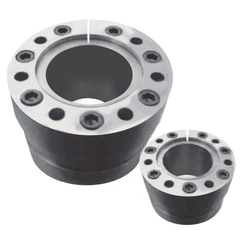
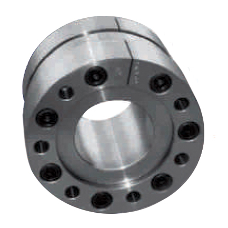
The 30 Flange coupling consists of 2 connecting flanges -10 and 20, which are locked onto the shafts by the integrated 1014 locking ring, which transmits the torque by friction. The 30 coupling can accommodate bore diameters from 50 to 290 mm. All the parts of the 1014 locking unit are split and have self-locking taper. No Fretting corrosion will occur on the locked contact surface.
| Size | Bore Length | Screw Size | Screw TA Nm |
| 50/70 | 75 | M10 | 83 |
| 70/90 | 90 | M12 | 145 |
| 90/115 | 100 | M14 | 230 |
| 115/140 | 100 | M14 | 230 |
| 140/170 | 128 | M16 | 355 |
| 170/210 | 128 | M16 | 355 |
| 170/210 | 128 | M16 | 355 |
| 210/250 | 150 | M20 | 650 |
| 250/270 | 158 | M20 | 650 |
| 270/290 | 158 | M20 | 650 |
Applications
- Pumps
- Compressors
- Motors
- Centrifuges
- Conveyor Systems
- Mixing Equipment
- Agitators
- Power Transmission Equipment
- Rolling Mills
- Generators
- Printing Presses
- Marine Propulsion Systems
- Paper Mills
- Textile Machinery
- Oil & Gas Equipment
For more products:
Shaft Encoders
Industry Standard Equipment
Fluid Coupling
Repairs and Balancing
Conveyor Backstop
Conveyor Slow Speed Hold backs and Backstops